In part one of this series, we addressed the basics of microgrid technology and its potential to reshape our energy landscape. In part two, we embark on a deeper journey, exploring the practical applications and use cases of microgrids. We’ll examine how the real-life implications and opportunities presented by microgrids are poised to revolutionize the way we power our communities and businesses.
Peak Demand and Net Metering
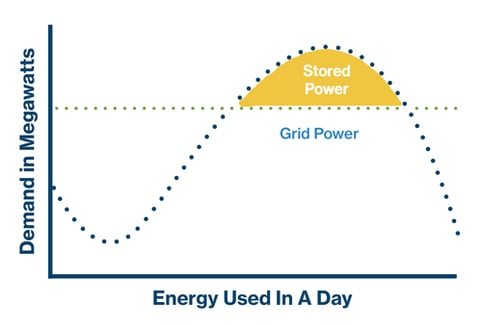
From a utility perspective, “peak demand” refers to the period of highest electricity consumption within a given time frame, typically occurring during times of high energy usage, such as hot summer afternoons or cold winter evenings. Peak demand often places significant stress on the grid infrastructure and can lead to higher operational costs for utilities, due to the need for additional generation capacity. To manage peak demand, utilities may implement demand response programs or charge higher rates during peak hours to incentivize consumers to reduce their electricity usage.
For example, the utility company Rocky Mountain Power, considers peak demand to be 1pm-8pm from June to September, while in the winter months, peak demand is 8am-10am and 3pm-8pm. It’s during these times that residential customers can see an increase between 1.3 and 4.5 cents/kWh, while commercial customers can expect to pay 1.2-2x their normal rate.
Net metering, on the other hand, is a billing mechanism used in solar energy applications that allows consumers who generate their own electricity, typically through solar panels, to receive credit for the excess electricity they feed back into the grid. When they generate more electricity on-site than is consumed, the excess energy is exported to the grid, and the consumer receives credits on their utility bill for the kilowatt-hours (kWh) exported. These credits can then be used to offset the cost of electricity consumed from the grid when solar production is insufficient, effectively allowing consumers to "net out" their electricity usage over a billing period.
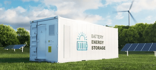
Programs like these encourage the use of solar energy systems so they can generate their own renewable electricity while remaining interconnected to the grid for reliability. Net metering also applies to power fed to the grid through BESS (Battery Energy Storage System), fuel cell, or any numbers of DERs (distributed energy resources) connected to the grid.
Microgrid Structure
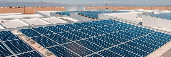
Let’s start with a simple example of a microgrid application. We will utilize a 250 kW solar array, diesel genset, and a 250 kW BESS.
In normal operation, the utility is charging the BESS during the day or non-peak demand hours. The load is being reduced with solar production, and excess solar is also going to the battery to charge it. If the BESS battery is full, the solar is back feeding the grid, via net meter, and the owner is gaining credit from the utility. The diesel genset is in standby mode until needed.
Use case/Application
Scenario 1:
Let’s assume the above paragraph is true. Say our 250 kW battery is sized for 4 hours of runtime. The facility we are powering draws 125 kW of load between 1pm - 8pm. Utility is operational, battery is fully charged, 1pm - 8pm is peak demand hours, resulting in a 1.5x multiplier/kWh used. From 1pm – 8pm, the BESS will discharge to 20%, depending on load, shaving the kWh used by 80%. This means, that from 1pm - 8pm, instead of paying 1.5x the normal cost /kWh, you are now “netting” a credit of 1.5x, because at that time, it is the going rate/kwh. From an ROI perspective, gaining this credit daily helps significantly reduce the initial upfront investment required. Once peak is over, the BESS begins to charge on utility through the night and into the morning, at the cheapest rate available and the whole process starts again.
Scenario 2:
The utility feed sees a blip in voltage greater than 10%. Without a BESS, this will kickstart your genset to turn on and ramp up to load. With a BESS, the load simply switches from utility to BESS, the genset stays off until a critical point is reached in BESS charge levels, and then the genset will kick on. Utah has a very stable grid, but markets in California, Texas, and New York can see blips daily. Reducing genset starts directly reduces carbon emissions, and saves the components on the generator from mechanical wear.
Most outages we see are small scale that do not require a full generator start. Today, most controls and logic have a very low tolerance to voltage sags and dips, and will auto start the generator within 3 millisecond of seeing a voltage problem. Adding a BESS into this system will allow a much larger time delay on gen starts and ultimately save maintenance and operational costs over the genset’s lifetime. We are not at the point where a BESS can completely replace a generator, but it allows for down-sizing and decrease operational costs. Another point to consider is the controls behind a diesel generator and BESS system. You can favor the BESS or the generator all through controls schema, it just depends on the priorities of the end user.
Scenario 3:
Utility goes down. The BESS is kicked into islanding mode, which is achieved through controls and circuit breakers, and the critical load gets transferred to the BESS. Depending on the runtime specified in the BESS, this will eliminate a generator start for the duration specified on the BESS. If utility is not restored, then a gen start will be required. The added redundancy in this scenario cannot be understated. You can treat the BESS as an uninterruptible power supply (UPS), you can backup your UPS via BESS. Many configuration options exist in this instance and allow end users to be flexible when deciding how to manage outages. This scenario is where the importance of controls and isolation needs to be highlighted.
Electronic isolation and controls ensure the safe and efficient operation of microgrid components and prevent system failures and electrical hazards. Through advanced control algorithms and monitoring systems, operators can oversee the performance of microgrid assets in real-time, and make adjustments to maximize efficiency and reliability. Additionally, with the addition of an isolation switch, it is necessary for mission critical environments to include a maintenance bypass into the isolation loop. This prevents single points of failure and allows for on-line maintenance and equipment changes. Ask your local DVL sales representative about our Power Engineering and Controls team to learn more.
Scenario 4:
Let’s get creative with the layout of a microgrid. So far, we’ve been discussing small amounts of renewable energy distributed on the site. We are now going to add some Hydrogen (H2) to the equation. Say we have 250 kW of a PV array, there is also a 250 kW BESS. Cue the addition of a hydrogen electrolyzer, which is a device that utilizes electricity to split water molecules (H2O) into hydrogen (H2) and oxygen (O2) through a process called electrolysis. This technology enables the production of hydrogen gas, which can be used as a clean and sustainable energy carrier for various applications, including fuel cell vehicles, energy storage, and industrial processes. Hydrogen electrolyzers play a key role in the transition to a low-carbon economy by providing a renewable source of hydrogen fuel without producing greenhouse gas emissions.
We are now feeding the electrolyzer a steady supply of water and voltage (through a joint effort of utility and photovoltaic [PV] array) and we’re now producing hydrogen on-site. We then need to compress it to store it in a tank, which, again, can be achieved through utility or PV. We will then add a 1.3 MW fuel cell into the equation. H2 (hydrogen) is approximately 3x more energy dense/liter than diesel fuel. Which means if a 10,000 gallon tank of diesel could provide 36 hours (3 days) of runtime, a 10,000 gallon tank of hydrogen could provide you with 108 hours (9 days) of runtime. The capacity difference is enough, in my opinion, to get the end user to switch, but on top of that, here is where you start seeing the building blocks of a self-sustainable BYOP (bring your own power) solution, where you’re powering yourself and capable of creating more fuel on-site.
This list of scenarios is by no means complete, but it helps to illustrate why a microgrid structure will be critical to the data centers of tomorrow. One more note on these systems is, while they may be expensive, end users are not the only ones who stand to reap benefits. Utility providers are very motivated to help support the build out of these energy programs. The more DERs that utilities have a feed into, the less they need to buy power from other supporting grids. Rocky Mountain Power has put approximately $5,000,000 into a Wattsmart battery incentive program that is looking to subsidize grid size BESS solutions.
You can get an upfront incentive when you enroll, and you get monthly credits for supporting the grid. While it may seem like a lot of money to offer end users, the end goal of the utility is increasing their capacity without building a new power plant. This allows for a truly rare “win-win” situation for utility provider and end user.
Product Offering
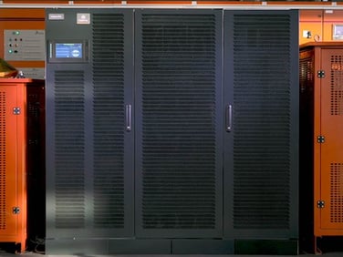
Vertiv Dynaflex+ BESS. Available in 250 and 500 kW or 1, 1.5, and 2 mW. These batteries can be paralleled in groups up to 4 of the same kind, which would allow for up to 8 mW of storage per chain. Included in the BESS is a bi-directional inverter, for charge and discharge. These are containerized solutions capable of being dropped into any campus. They offer Li-Ion battery chemistry with a full suite of monitoring and controls. They also include a liquid cooling loop and can be placed in almost any environment. The Dynaflex is compliant with all UL fire listings, as well as the 9540 for Li-Ion batteries. And, as previously mentioned, peak shaving is a great use-case for these systems, as well as emergency power, solar energy storage and more.
Generac also has BESS offerings in the 500 and 1000 kW range. They include the full suite of features listed above.
One thing to note, is the Dynamic Online Mode available for addition on Vertiv/Liebert EXL S1 UPS. It will treat the UPS as a BESS and create a schedule that allows for the discharge of the UPS batteries to a setpoint throughout the day to create a “revenue” generating asset that is deployable at any time. Essentially a “Micro” BESS.
The way to prepare our industry for its best possible future is to not just follow status quo, but to question, learn, and educate ourselves, so we can understand the complexities of sustainable energy solutions. The scenarios outlined here illustrate the tangible benefits and opportunities offered by microgrids and battery energy storage systems. From managing peak demand to integrating renewable energy sources and more, we see the potential for a brighter and more sustainable future.
Please stay posted for the third and final part to this blog series, out in May,
which will explore electric vehicle (EV) charging infrastructure.
Have a question or comment about this blog?
Reach out to blog author Alexander "D'Angelo" D'Angelo, Power Systems Sales Engineer, (based out of our Salt Lake City office) at ADangelo@DVLnet.com.